Non-isolated UART communication
The UART communication interface was selected as the primary communication interface. UART is a good choice mainly due to its widespread use. Communication is asynchronous, where we do not need a clock signal, so only one wire is needed between the modules. The advantage of one wire is that it is cheaper than two and also more practical in the installation of the system. The cheapest possible components and also the minimum number of components are being used to make the communication possible. The biggest problems during the design of the communication interface were caused by the protection diodes on the processor pins, but in the end we were able to exploit their purpose in some way.
The Problem
The problem with cell modules is that processors are not powered from the same voltage source, but still have to communicate with each other. They are even powered with an offset voltages. Two neighboring processors have connected Vcc and GND pins. The model of this connection is shown in the figure below:
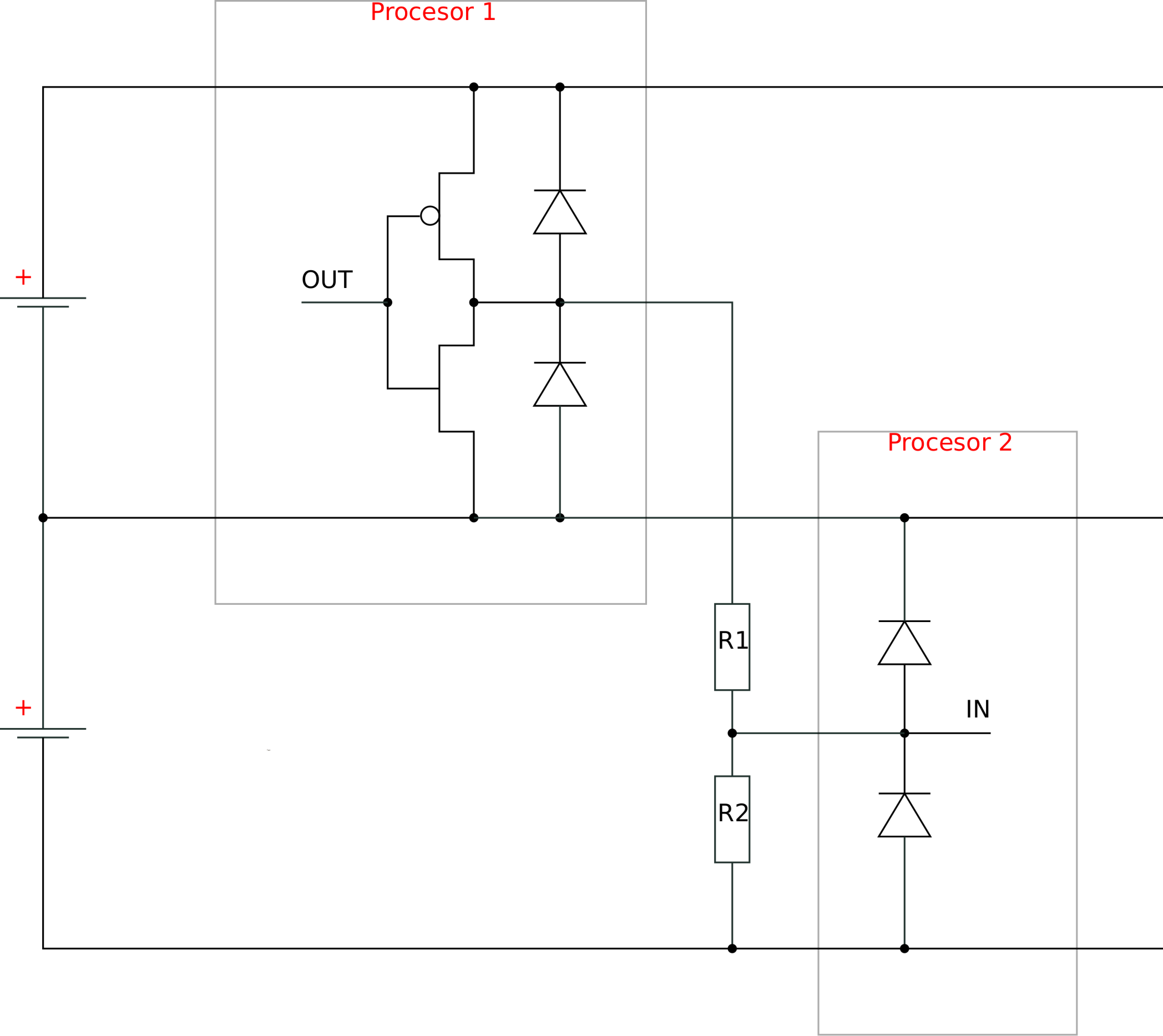
Lower processor (processor 2) can receive 2 different voltage levels from upper processors. The first level is at the output of logic 0 from upper processor. Upper processor reads this state as 0V, but for lower processor this is its own supply voltage or logic 1. No problems so far, we only get the reverse logic and all voltages are still in the operating range of both processors. At the second level output, logic 1 from the upper processor some problems occur. For the lower processor this level means its supply voltage plus the supply voltage of the upper processor. Now this level is no longer allowed. The voltage is just too high for lower processor. The challenge was how to adjust these two voltage levels to the lower processor so it can easily receive the signal from the upper processor.
There are many solutions that could work, but they are not in line with the requirements. The problem is that all solutions have at least one semiconductor element. A single semiconductor element would quickly raise the cost of the required components. However, with a clever use of processors peripherals it is possible to achieve a successful communication only with use of two external resistors. The resistors divide voltage, and limit current through the protection diodes.
The solution
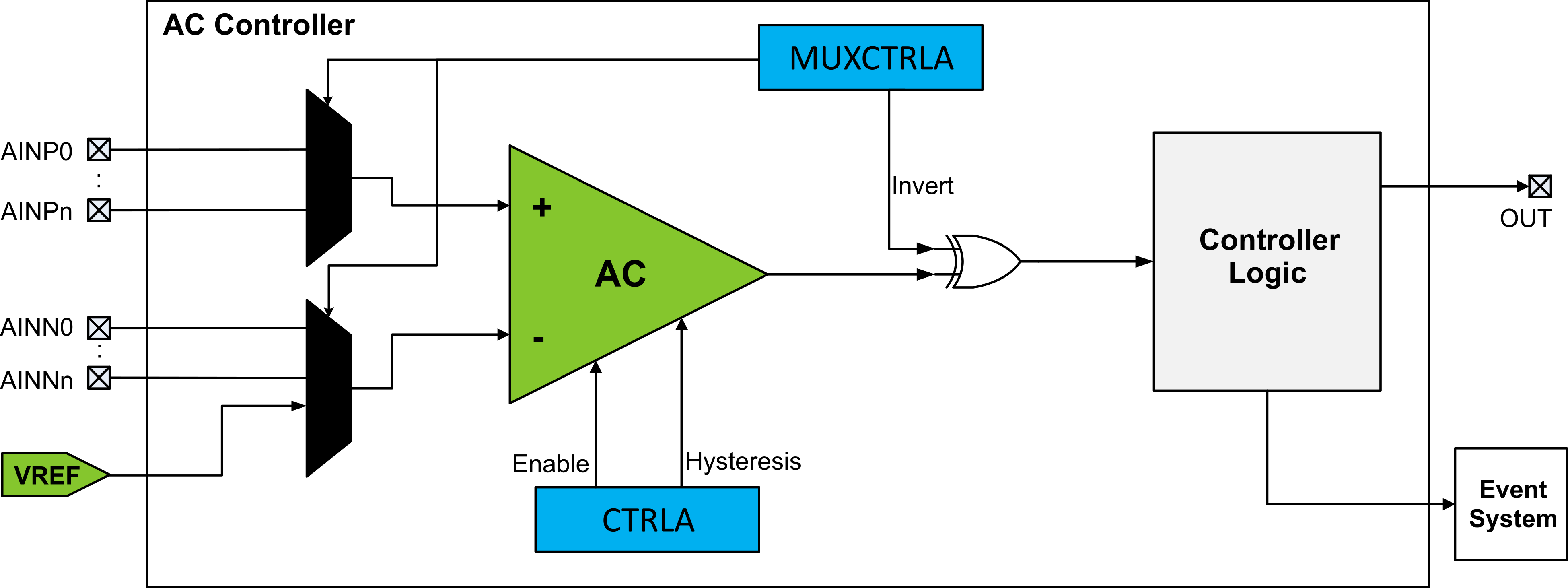
A build-in analog comparator (AC) is used to distinguish the signal level. The processor voltage supply is connected to the non-inverting input of the AC and 80% of the UART signal from the upper processor to the positive input. Resistors with large values were chosen for the voltage divider for two reasons. First, 80% of the signals voltage level is still too much for the lower processor. The current flowing through the protection diodes is limited by the use of larger resistors. Small current does not damage the diodes. The purpose of the diodes is only to keep the voltage within acceptable limits. The second reason is that we wanted to have as low static power consumption as possible, because the module is powered by a battery.
A more detailed explanation is needed to fully understand how communication works. The AC output indicates whether the UART signal voltage is less than or greater than the processor supply voltage. This is a very important piece of information that we need to get to the processor’s UART receiver. The processor allows us to connect the AC output to the physical output pin of the processor. This output pin can then be easily connected to the input pin of the processor on which the UART receiver is located. However, to be able to do that, we need both one free output pin and one free input pin. Selected processor has very few pins and we don’t have enough remaining free pins to make this solution feasible. A closer inspection of the “PORT” unit revealed that we only need a single processor input pin for both signals. The rest can be solved with a single if statement in software by changing the invert enable signal of the processors input pin.
A very similar method with the AC is used to detect zero cross of mains supply. However, the described use of AC on a cell module is a bit more demanding. We didn’t see anyone using an AC to trigger the UART receiver. This area of the system required a bit more in-depth research. The solution raises two questions: “Will the communication work over the entire BMS operating voltage range from 1.8V and up to 5.0V?”, and “How will communication be resistent to interference?”.
Resistor divider
The resistor divider division factor if very important. It will ensure that the communication will operate in the entire voltage range of the BMS. At first, this seems like a simple problem, but like so many others, it quickly turned out to be a little more difficult. We previously mentioned that the UART signal levels from the upper module are compared to the cell voltage, which is not quite true. If that would be possible, it would be much easier. Once again it turns our we don’t have enough free pins available. To overcome this problem we utilize built-in voltage reference to approximate the supply voltage. Connected UART signal is on the positive AC input, and the voltage reference of 4.3V on the negative input. The selected reference is the highest available in the processor. The highest reference will be the closest to supply voltage in the entire voltage range of the processor (1.8V - 5V). We don’t use the reference for its true purpose, but only to give us an approximation of the supply voltage. The reference is only valid when powered by 4.8V or more. With a cell module, this will never happen. The voltage reference will always be in its “linear” range. Normally, the reference is always used in the “saturated” state. In its linear range, the reference voltage output will be a few percents below the supply voltage all the time. This is very useful, because the voltage reference is going to give us a sufficient approximation of the supply voltage, and we do not need an additional processor input. Due to a little bit different use of the voltage reference, we do not have enough data, because such use is not documented in the processors datasheet. We needed a snapshot of the reference output in the entire voltage range of the processor. The recorded characteristic is shown in the figure below.
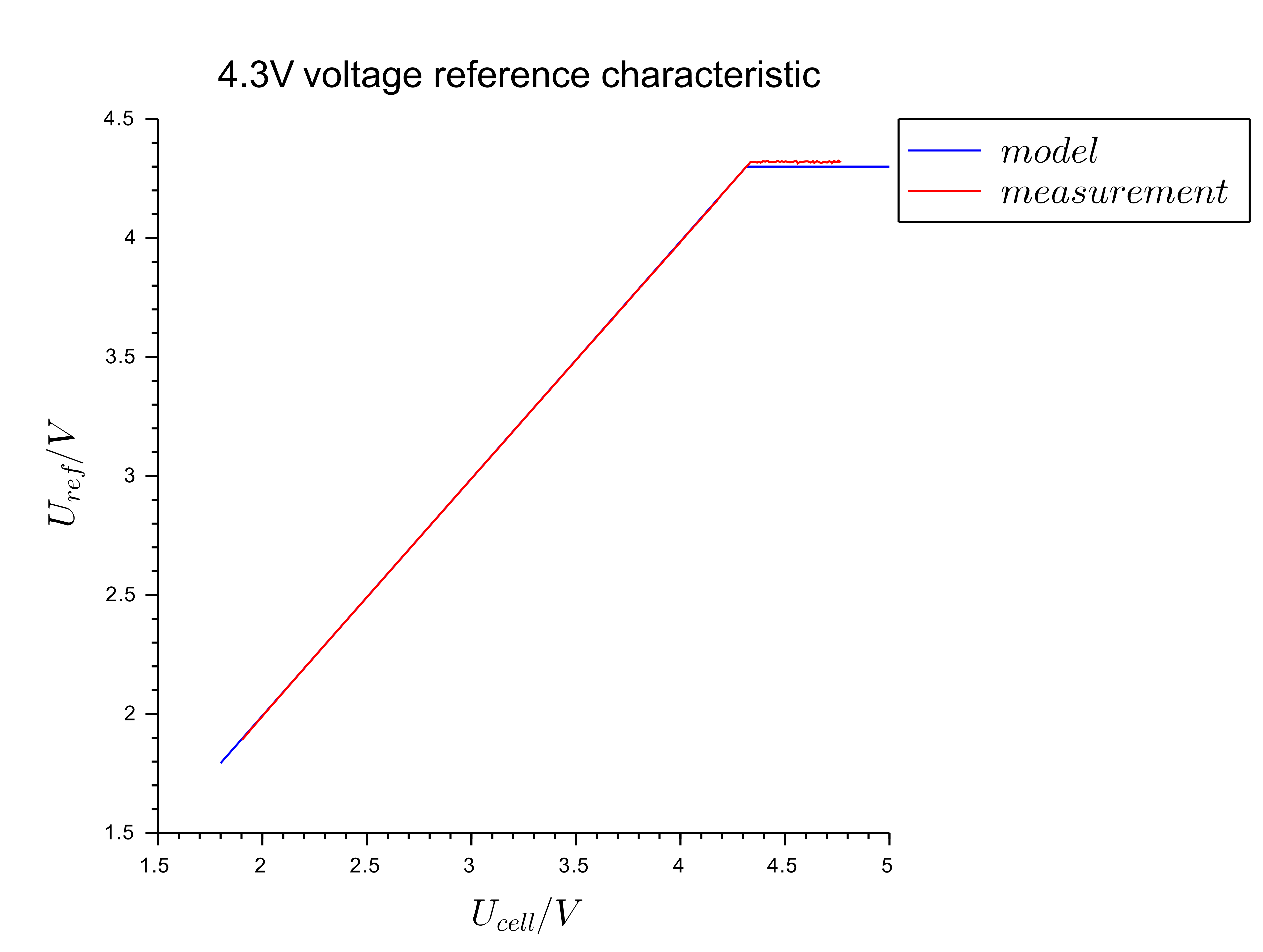
The characteristic was recorded with a built-in ADC and by changing the processor supply voltage. From the characteristic, a simplified reference model was created, which is shown by the equations.
To identify a low signal level, the output from the voltage divider must be lower than the reference voltage, and to detect a high level, it must be higher. These situations are described by the following inequalities:
From both inequalities we can express the divisible relation r and form one single inequality.
We can now insert real numbers into the inequality. We need to insert the voltages at which we get the smallest range of the voltage divider ratio. By solving these two inequalities, we have obtained only the range in which the division ratio must be. Due to the nonlinear characteristic of the voltage reference, the resistance tolerances, and other nonlinearities of the system, we cannot determine the perfect division ratio. The use of resistors with low tolerances is also not desirable, because these resistors will increase the price of the components. We even have to look at the voltage range of the system for all possible deviations of the voltage divider ratio due to resistance tolerances. For that purpose, we need equations that describe the voltage differences between the signal levels and the voltage reference. The difference between logic output 1 from the upper processor and the reference voltage of the lower processor must always be positive and vice versa for logic output 0, where the difference must always be negative. This is nicely described by the equations below:
Because the cell module uses an AC and UART receiver on the same processor input, it is important that this input always has the same and defined state. We want the processors input always to have a logical state of 1. This criterion must also be considered and is given to us by the equation:
In all three above equations, we have a division ratio. Due to the resistance tolerances, the division ratio is not an exact value, but is located on the certain interval. The next equation gives us a division ratio error due to the influence of resistance tolerances, where e1 is the tolerance for R1 in percent and e2 for the resistance R2
With this division ratio error factor, we can extend previous inequalities. The graph in the figure below shows all possible solutions of the inequalities. The most critical points are those closest to the X axis of the graph. The points can be identified very quickly. The critical points in the low and high signal curves must both be equidistant from the axis of the graph.
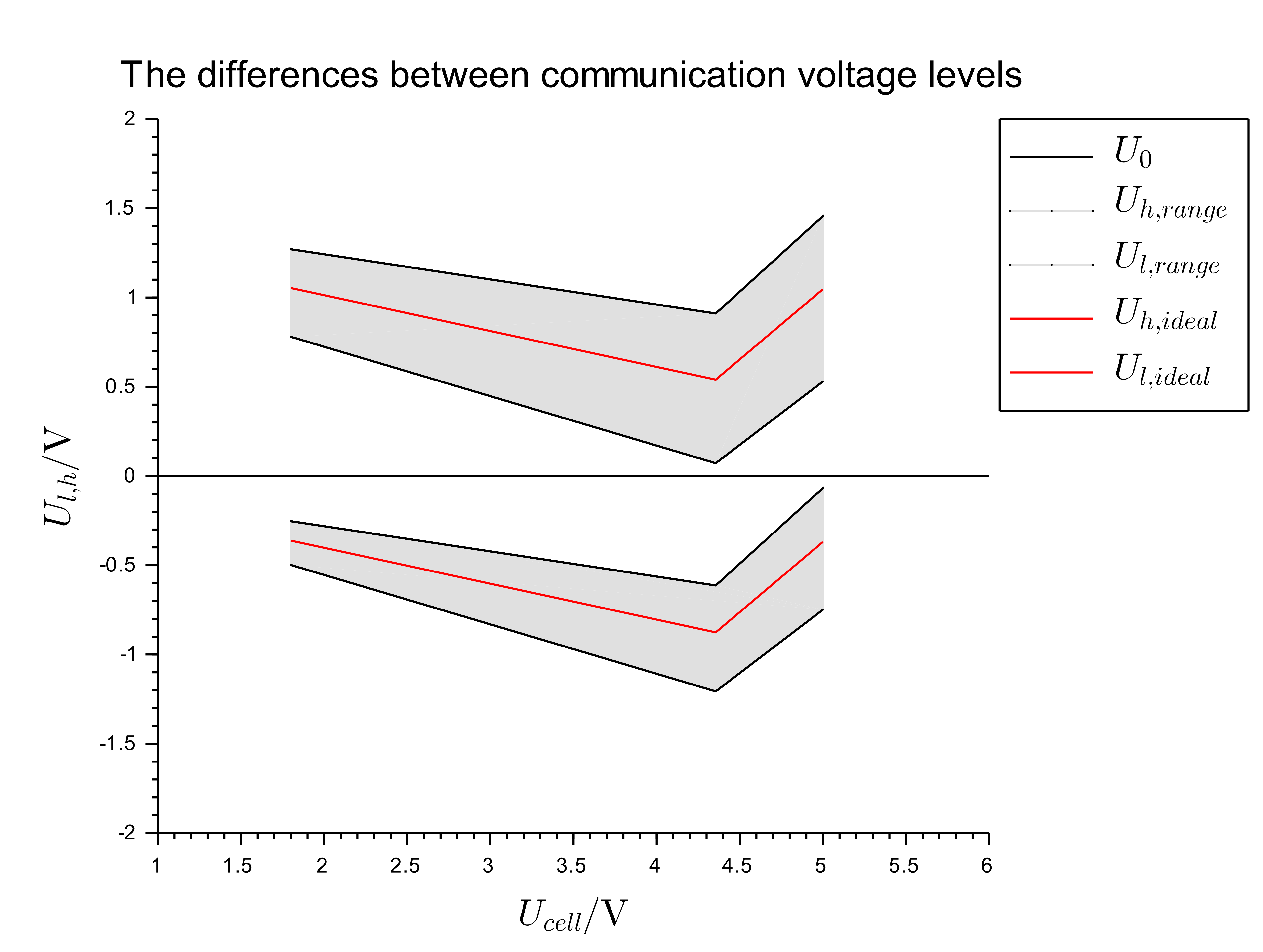
If we combine all the conditions and insert all the parameters, we finally get a division ratio of 0.79. The division ratio can be realized using resistors from the E6 scale with 20% tolerances.
AC output status bit as UART signal
The main problem was programmatically creating a connection between the AC status register and the UART receiver. The AC output status is written in one of the bits of the AC status register and the state of this bit needs to be transferred to the UART receiver. After analyzing the “PORT” peripheral unit, we found out that the “Invert Enable” signal can be used to programmatically trigger the UART receiver.
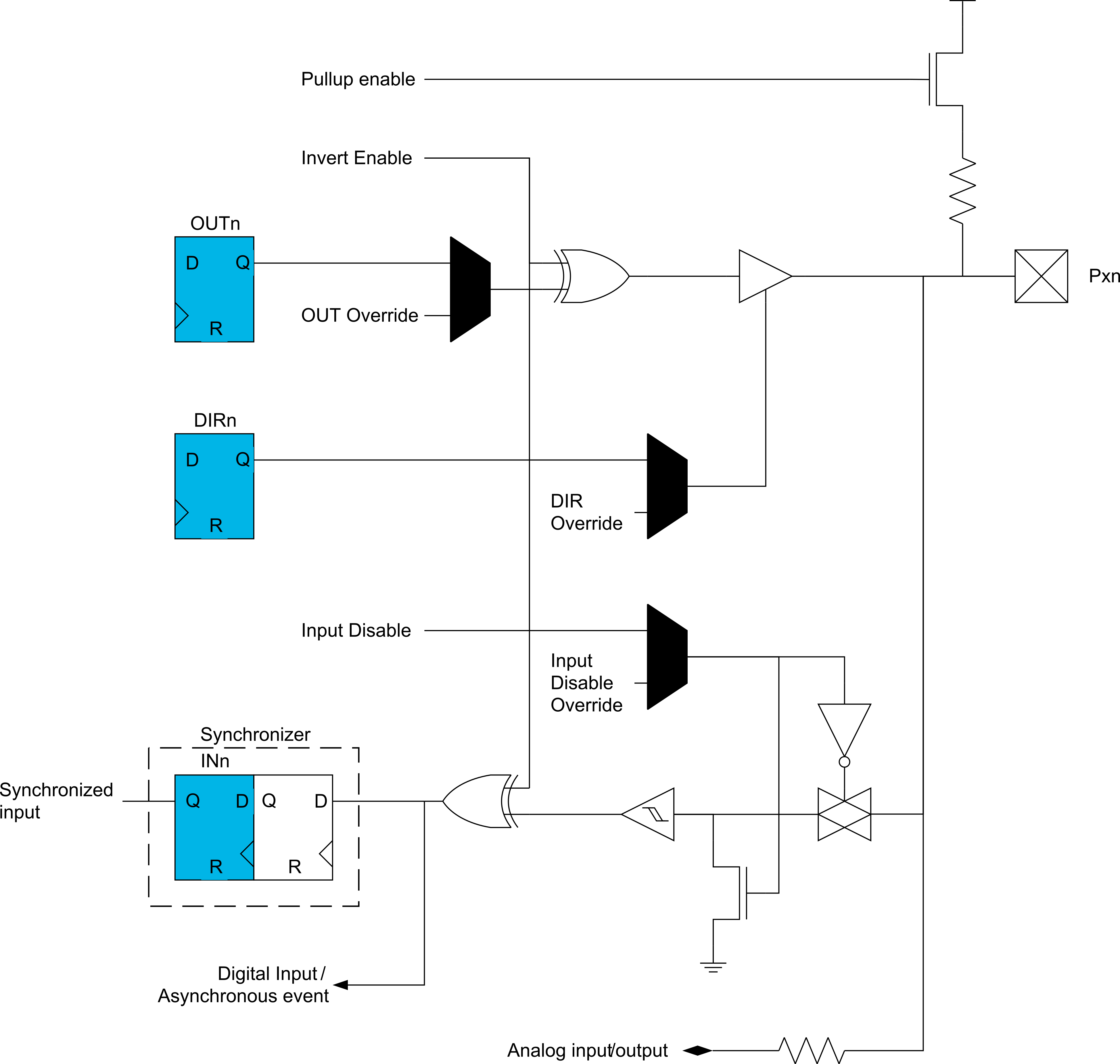
We need to ensure that the signal changes quickly. This was achieved by using interrupts. Each time the AC output is changed, it triggers an interrupt. In the interrupt routine, the “Invert Enable” signal is then quickly set to the correct value. The interrupt routine used is presented in the code section below:
ISR(AC0_AC_vect)
{
  /* Clear int. flag */
  AC0_STATUS = AC_CMP_bm;
  /* Invert pin input */
  if(!(AC0_STATUS & AC_STATE_bm)) PORTA_PIN7CTRL = PORT_INVEN_bm;
  else PORTA_PIN7CTRL = 0x00;
}
This part of the program proved that the an idea of an non-isolated UART communication works. Later on, other tests have shown that the method is also reliable.